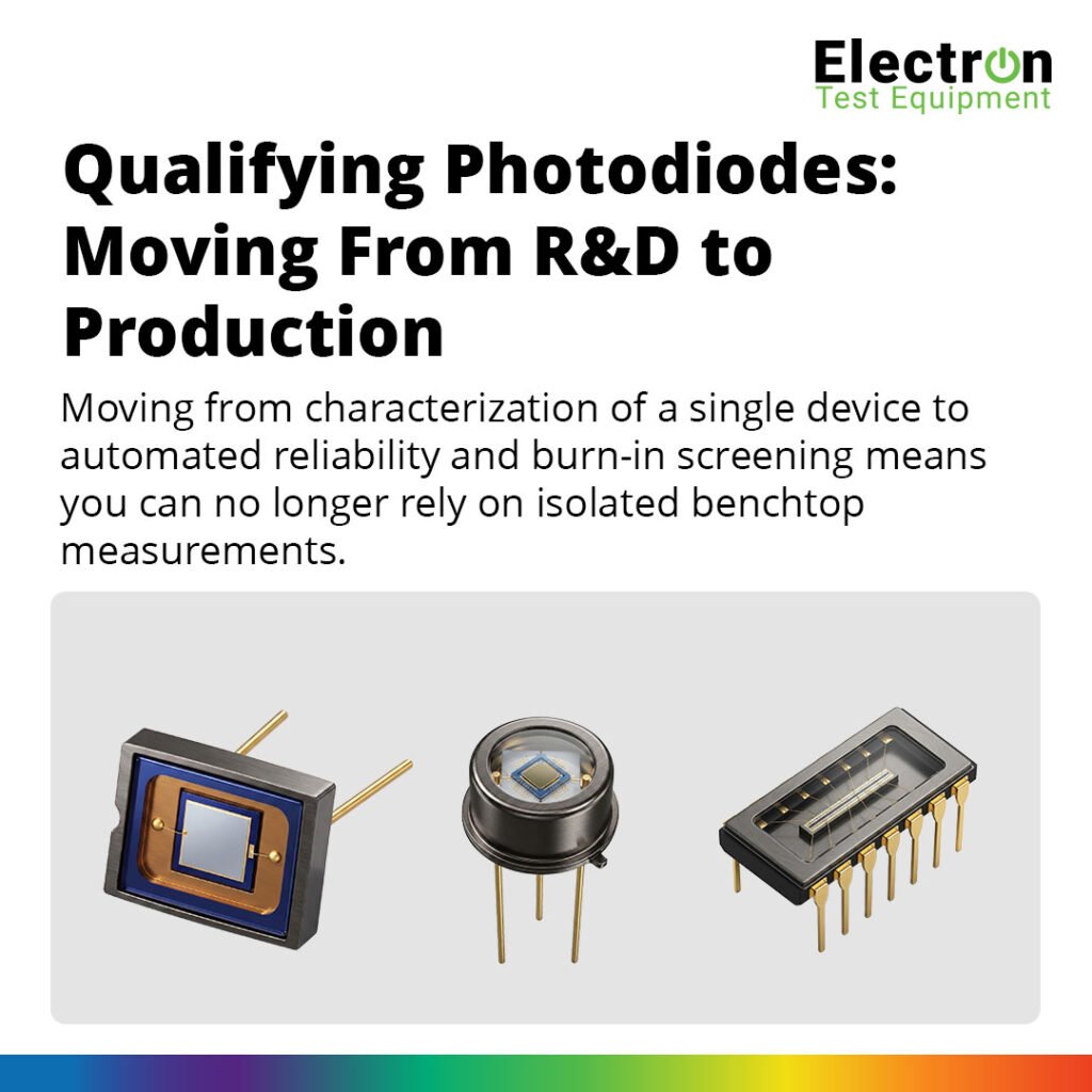
Qualifying photodiodes for telecom, defense, robotics, or medical applications places two demands on your test process that rarely coexist on a typical lab bench: picoampere-range measurement accuracy and high throughput, hundreds of devices per shift.
Moving from R&D device development into rigorous reliability and burn-in screening means you can no longer rely on testing a single isolated device; meeting these standards requires characterizing statistically significant sample sizes of at least 32 to 64 units concurrently, a testing volume that requires scalable automation.
This article walks you through the critical measurement parameters, the instrument stack required to capture them, the throughput mechanics of production-grade automation, and how to specify a custom photodiode characterization system matched to your device and volume requirements.
Whether you’re evaluating silicon PIN detectors for defense applications or InGaAs receivers for 5G telecom infrastructure or AI data centers, the framework is the same: get the measurements right, build the instrument stack that supports them, and match your automation tier to both your R&D team’s workflow and your production volume.
6 Parameters Every Photodiode Test System Must Measure
Selecting a photodiode test system starts with understanding what the device actually needs to prove. There are 6 core parameters that any credible system must capture. Each one maps directly to a real application requirement, and skipping any of them leaves gaps that will surface as field failures or qualification rejections.
1. Responsivity
Responsivity, measured in amps per watt (A/W), shows how much electrical current a photodiode produces for a given amount of incoming optical power. Because a device’s performance changes depending on the wavelength of light, a test system must run a complete spectral sweep to accurately map this metric across its operating range. For factory lot acceptance, getting this baseline measurement correct is mandatory.
2. Quantum Efficiency (EQE & IQE)
Quantum efficiency converts performance into an electron-per-photon ratio to evaluate device physics. Test systems look at External Quantum Efficiency (EQE)—which measures performance relative to all incident photons—and Internal Quantum Efficiency (IQE), which accounts only for absorbed photons. EQE serves as the required deliverable for official datasheets and production screening.
3. Dark Current and the Noise Floor
Dark current is the small leakage current that flows through a photodiode even when there is no illumination, directly establishing the noise floor for low-light detection. Typical operating ranges span from 0.1 to 1 nA for silicon detectors, while InGaAs receivers for telecom applications commonly run between 1 and 3 nA at a specified reverse bias. Capturing these low levels accurately during production screening requires a high-precision source measure unit or a dedicated picoammeter with sub-fA resolution.
4. Noise Equivalent Power (NEP) and Detectivity
Noise Equivalent Power and specific detectivity are derived directly from dark current and bandwidth. They quantify the minimum detectable optical signal and serve as the critical figures of merit that qualification engineers in defense, medical, and telecom applications scrutinize most closely to ensure high-sensitivity performance.
5. Bandwidth and Rise Time
For high-speed photodiodes used in telecom, data centers, or radar systems, measuring bandwidth and rise time is just as important as checking light sensitivity. Because internal circuit capacitance and test cables can artificially slow down results, the hardware stack must be calibrated to remove the equipment’s own limitations from the final high-frequency measurement.
6. Linearity Verification
Linearity verification ensures that photocurrent increases in direct proportion to optical power across the entire operating range. This step is vital for factory calibration and lot tracking because a detector that compresses at moderate light levels creates gain errors. These errors remain hidden during a basic single-point light check, but they can cause system-wide failures in the field.
Photodiode Test System Instrument Stack
No single instrument captures all six parameters above. A full characterization stack combines precision electrical instruments, a calibrated optical path, and environmental control, all tied together by automation software. Understanding each layer helps you specify the stack correctly rather than discovering gaps after integration.
Electrical Instruments: SMU, Picoammeter, and C-V Analyzer
The source-measure unit (SMU) handles biased I-V sweeps, providing the reverse bias range the device needs while measuring current simultaneously. For photocurrent and dark current at the picoampere level, a dedicated picoammeter with guarded triax cabling is necessary. Unguarded connections introduce leakage that drowns the measurement entirely.
When the test plan includes depletion characterization or bandwidth modeling from junction capacitance data, a dedicated C-V analyzer is added to the stack. Many production test programs run I-V and C-V through a switch matrix so the DUT doesn’t need to be reconnected between measurement modes.
Optical Path: Light Source, Monochromator, and Reference Detector
The optical side of a QE tester setup typically uses a broadband lamp coupled through a monochromator for spectral sweeps, or a tunable laser and LED sources for specific wavelengths and speed measurements. A calibrated reference detector with traceable spectral responsivity establishes the incident optical power at each wavelength.
Coupling optics, lenses, apertures, fiber assemblies, and alignment stages, deliver a known spot to the DUT under test. The QE calculation is straightforward once power and current are both measured at each wavelength, but the accuracy of the result depends entirely on the calibration quality of the reference detector and the stability of the optical alignment during the sweep.
Temperature Control and Environmental Access
Any production qualification program referencing Telcordia GR-468-CORE or MIL-STD-883 requires environmental test coverage.
Typical conditions include:
- Temperature cycling from -40°C to +85°C
- High-temperature operating life at 85°C for up to 2,000 hours
- Humidity stress at 85°C/85% RH (As required)
The thermal chamber or TEC temperature-controlled station must provide optical access so that responsivity and dark current measurements can be taken at temperature without breaking the measurement setup.
Lab Bench Setup vs. Production-Grade Photodiode ATE: Where the Real Gap Shows Up
A bench setup with a precision SMU, fiber-coupled laser, and a good picoammeter is excellent for device development, it gives you flexibility to probe any parameter at any bias point and produces a valid I-V curve and responsivity number quickly.
For example, some bench top setups would use a, Keysight B2980C for photodiode testing however the limitation is that it can only be customized for testing 1 photodetector in addition to combining with other external devices.
That changes entirely when the goal shifts from understanding one device to qualifying 32 or 64 simultaneously and scaling to over 1000 for production.
Where Manual Bench Setups Hit Their Limits
Manual bench testing of individual photodiodes introduces alignment drift between devices: every time an engineer couples a fiber to a new DUT, the coupling efficiency shifts slightly. Those shifts translate directly into responsivity errors that accumulate across a lot. Operator-to-operator variation compounds the problem.
Throughput data makes the cost concrete: an automated photodiode test system can screen roughly 297 devices per hour on basic dark current and responsivity, while manual single-device testing typically achieves around 30 devices per hour.
At a few hundred devices per day, you’re burning through multiple shifts to screen a single lot, and measurement correlation between devices tested at the start of the shift and the end becomes unreliable.
What Production-Grade ATE Systems Add
A production semiconductor photodiode tester replaces every manual step with a scripted, repeatable process: automated fixture contact or optical coupling, pre-loaded instrument states for each measurement, and software-controlled pass/fail limits with direct output to factory data systems.
Fixture repeatability eliminates the alignment drift that corrupts lot-level yield correlation on a manual bench. Per-channel calibration ensures that a device tested on channel 4 gets the same measurement as one tested on channel 12. These are not incremental improvements over a bench setup; they are a different class of tool designed for a different job.
How Automation Drives Throughput and Measurement Repeatability at Scale
The operational mechanics of automation, how it compresses cycle time, eliminates human variables, and generates traceable yield data, are what let you set realistic expectations when specifying a system. Getting those details right upfront prevents costly redesigns after deployment.
Test Sequence Design and Cycle Time Reduction
Sequence engineers reduce cycle time by pre-configuring instrument states, minimizing settle delays, and limiting production screens to the minimum measurement set required for release. A basic dark current and responsivity pass/fail at two or three bias points runs far faster per device than a full spectral QE sweep across 50 wavelength points.
The tradeoff is explicit: deeper screens catch more marginal devices but reduce station utilization. The right screen depth is defined by your application’s field failure risk, not by what the instrument is capable of measuring.
Handler Integration and Parallel Channel Testing
Scaling from R&D bench testing to high-volume production requires more than fast instruments; it demands automated handling and robust data tracking. To maximize throughput and ensure compliance, modern photodiode test systems rely on two major operational pillars: parallel hardware integration and automated data traceability.
Handler Integration and Automation:
- Mechanical Handlers: Eliminates manual loading and unloading times, which are typically the biggest bottlenecks in semi-manual lab setups.
- Parallel Channel Testing: Runs multiple photodiodes simultaneously using independent optical and electrical paths for each channel, multiplying testing throughput based on the total channel count.
- Fixture Precision: Achieving reliable multi-channel scaling requires precision-machined alignment features, matched fixture optics, and independent per-channel calibration.
- Thermal Compensation: Uses closed-loop tracking algorithms to maintain optical coupling consistency and compensate for thermal drift throughout long production runs.
Repeatability, Yield Correlation, and Data Traceability
- Scripted Test Sequences: Removes human error and variable handling from the testing process to ensure 100% test repeatability.
- Compliance Data Infrastructure: Captures structured data logs required by qualification authorities when reviewing reliability submissions under MIL-STD-883, Telcordia GR-468-CORE, or AEC-Q100 standards.
- Real-Time Outlier Detection: Flags failing or anomalous devices instantly during active burn-in runs rather than waiting for post-test analysis.
- Actionable Feedback Loops: Provides engineering teams with immediate data on process drift, allowing them to catch manufacturing issues early instead of discovering them weeks later in failure reports.
Specifying a Custom Photodiode Test System
When the device class, package geometry, and throughput target are defined, the next step is specifying a photodiode reliability and test system that matches them precisely. This is where off-the-shelf test equipment consistently falls short for production qualification programs.
Why Catalog Test Equipment Falls Short for Production
Standard catalog testers are designed for flexibility across device types, not for the specific package geometry, optical coupling architecture, or throughput target of a given production line.
When you force a general-purpose instrument stack onto a production fixture designed for a non-standard device, you accept alignment compromises, degraded coupling efficiency, and integration overhead that absorbs any cost savings the catalog price appeared to offer.
DUT boards, fixture jigs, and coupling optics must be engineered for the actual device dimensions, pin-out, and optical interface.
How Electron Engineers Custom Photodiode ATE Systems
Electron designs photodiode test systems from the ground up for each client’s device package, test parameters, throughput target, and compliance standard. Their systems support simultaneous testing from 32 and 64 devices used in R&D to over 1,024 devices for production, with custom DUT boards and fixture designs engineered for the actual device under test.
Multi-standard compliance covering MIL-STD-883, Telcordia GR-468-CORE, and IEC is built into the system architecture, not retrofitted. The real-time software interface supports third-party data reporting and configuration tools so the system integrates with existing factory data infrastructure without custom middleware.
Electron also handles commissioning, operator training, and ongoing engineering support, and provides photodiode test system documentation to simplify handover, so the system arrives ready to run qualification programs rather than requiring a months-long integration effort before first use.
Choosing the Right Photodiode Test System for Automated Testing
Choosing the right system comes down to a clear set of engineering requirements: what parameters your device must prove, what instrument stack captures those parameters accurately, and whether your volume and repeatability targets call for manual bench testing or an automated system.
When transitioning into development work that demands fast, flexible characterization alongside formal qualification, modern automated test equipment (ATE) systems typically start at a batch capacity of 32 or 64 devices.
In our experience, teams moving from single-device semiconductor reliability and testing, characterization, and burn-in into high-volume screening often underestimate two major pitfalls: the cost of correlation errors that accumulate on manual setups, and how difficult it is to adapt general-purpose instruments into a specialized production fixture. The throughput gap alone, which is roughly a 10x multiplier between manual and automated screening, easily justifies the investment at any meaningful production volume.
If you are specifying a photodiode characterization and screening system that requires automated testing and qualification, talk to Electron to see how our custom engineering solutions fit within your technology stack (see our company overview). Our team works directly from your device package specifications, test parameter requirements, and throughput targets to design a custom photodiode test system built for your exact application.